- 您现在的位置:买卖IC网 > Sheet目录2006 > LTC2492IDE#TRPBF (Linear Technology)IC ADC 24BIT DELTA SIG 14-DFN
LTC2492
20
2492fd
APPLICATIONS INFORMATION
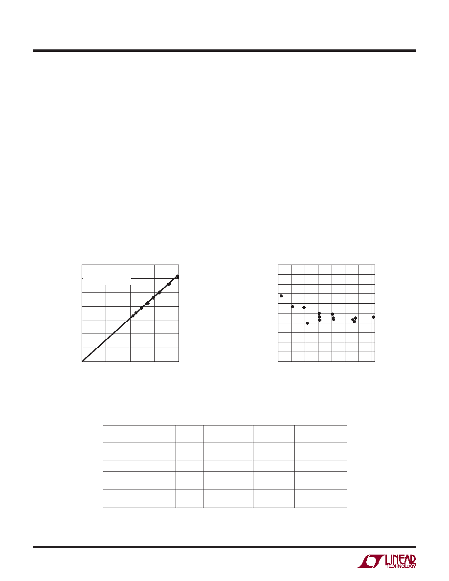
Figure 4. Internal PTAT Digital Output vs Temperature
from the output code (DATAOUT24) for a 5V reference
using the following formula:
TK = DATAOUT24/314 in Kelvin
If a different value of VREF is used, the temperature output
is:
TK = DATAOUT24 VREF/1570 in Kelvin
If the value of VREF is not known, the slope is determined by
measuring the temperature sensor at a known temperature
TN (in °K) and using the following formula:
SLOPE = DATAOUT24/TN
This value of slope can be used to calculate further
temperature readings using:
TK = DATAOUT24/SLOPE
All Kelvin temperature readings can be converted to TC
(°C) using the fundamental equation:
TC = TK – 273
SERIAL INTERFACE TIMING MODES
The LTC2492’s 4-wire interface is SPI and MICROWIRE
compatible. This interface offers several exible modes
of operation. These include internal/external serial clock,
3- or 4-wire I/O, single cycle or continuous conversion. The
following sections describe each of these timing modes
in detail. In all cases, the converter can use the internal
oscillator (fO = LOW) or an external oscillator connected to
the fO pin. For each mode, the operating cycle, data input
format, data output format, and performance remain the
same. Refer to Table 5 for a summary.
Figure 5. Absolute Temperature Error
Table 5. Serial Interface Timing Modes
CONFIGURATION
SCK
SOURCE
CONVERSION
CYCLE CONTROL
DATA OUTPUT
CONTROL
CONNECTION AND
WAVEFORMS
External SCK, Single Cycle
Conversion
External
CS and SCK
Figures 6, 7
External SCK, 3-Wire I/O
External
SCK
Figure 8
Internal SCK, Single Cycle
Conversion
Internal
CS↓
Figures 9, 10
Internal SCK, 3-Wire I/O,
Continuous Conversion
Internal
Continuous
Internal
Figure 11
TEMPERATURE (K)
0
DATAOUT
24
60000
80000
100000
120000
140000
400
2492 F04
40000
0
300
200
100
20000
VCC = 5V
VREF = 5V
SLOPE = 314 LSB24/K
TEMPERATURE (°C)
–55
–30
–5
ABSOLUTE
ERROR
(°C)
5
4
3
2
1
–4
–3
–2
–1
0
120
95
70
45
20
2492 F05
–5
发布紧急采购,3分钟左右您将得到回复。
相关PDF资料
LTC2493IDE#TRPBF
IC ADC 24BIT DELTA SIG 14-DFN
LTC2494IUHF#TRPBF
IC ADC 16BIT W/PGA 38-QFN
LTC2495CUHF#PBF
IC ADC 16BIT W/PGA 38-QFN
LTC2496IUHF#TRPBF
IC ADC 16BIT DELTA SIG 38-QFN
LTC2498IUHF#TRPBF
IC ADC 24BIT 16CH 38-QFN
LTC2600IUFD#PBF
IC DAC OCTAL R-R 16BIT 20-QFN
LTC2602IMS8#TRPBF
IC DAC 16BIT DUAL R-R VOUT 8MSOP
LTC2604IGN-1#TRPBF
IC DAC 16BIT QUAD R-R OUT 16SSOP
相关代理商/技术参数
LTC2493CDE#PBF
功能描述:IC ADC 24BIT DELTA SIG 14-DFN RoHS:是 类别:集成电路 (IC) >> 数据采集 - 模数转换器 系列:- 标准包装:2,500 系列:- 位数:16 采样率(每秒):15 数据接口:MICROWIRE?,串行,SPI? 转换器数目:1 功率耗散(最大):480µW 电压电源:单电源 工作温度:-40°C ~ 85°C 安装类型:表面贴装 封装/外壳:38-WFQFN 裸露焊盘 供应商设备封装:38-QFN(5x7) 包装:带卷 (TR) 输入数目和类型:16 个单端,双极;8 个差分,双极 配用:DC1011A-C-ND - BOARD DELTA SIGMA ADC LTC2494
LTC2493CDE#TRPBF
功能描述:IC ADC 24BIT DELTA SIG 14-DFN RoHS:是 类别:集成电路 (IC) >> 数据采集 - 模数转换器 系列:- 标准包装:2,500 系列:- 位数:16 采样率(每秒):15 数据接口:MICROWIRE?,串行,SPI? 转换器数目:1 功率耗散(最大):480µW 电压电源:单电源 工作温度:-40°C ~ 85°C 安装类型:表面贴装 封装/外壳:38-WFQFN 裸露焊盘 供应商设备封装:38-QFN(5x7) 包装:带卷 (TR) 输入数目和类型:16 个单端,双极;8 个差分,双极 配用:DC1011A-C-ND - BOARD DELTA SIGMA ADC LTC2494
LTC2493CDEPBF
制造商:Linear Technology 功能描述:24bit Delta Sigma ADC Temp Sens LTC2493
LTC2493IDE#PBF
功能描述:IC ADC 24BIT DELTA SIG 14-DFN RoHS:是 类别:集成电路 (IC) >> 数据采集 - 模数转换器 系列:- 标准包装:1 系列:microPOWER™ 位数:8 采样率(每秒):1M 数据接口:串行,SPI? 转换器数目:1 功率耗散(最大):- 电压电源:模拟和数字 工作温度:-40°C ~ 125°C 安装类型:表面贴装 封装/外壳:24-VFQFN 裸露焊盘 供应商设备封装:24-VQFN 裸露焊盘(4x4) 包装:Digi-Reel® 输入数目和类型:8 个单端,单极 产品目录页面:892 (CN2011-ZH PDF) 其它名称:296-25851-6
LTC2493IDE#TRPBF
功能描述:IC ADC 24BIT DELTA SIG 14-DFN RoHS:是 类别:集成电路 (IC) >> 数据采集 - 模数转换器 系列:- 标准包装:1,000 系列:- 位数:16 采样率(每秒):45k 数据接口:串行 转换器数目:2 功率耗散(最大):315mW 电压电源:模拟和数字 工作温度:0°C ~ 70°C 安装类型:表面贴装 封装/外壳:28-SOIC(0.295",7.50mm 宽) 供应商设备封装:28-SOIC W 包装:带卷 (TR) 输入数目和类型:2 个单端,单极
LTC2494CUHF#PBF
功能描述:IC ADC 16BIT W/PGA 38-QFN RoHS:是 类别:集成电路 (IC) >> 数据采集 - 模数转换器 系列:- 标准包装:2,500 系列:- 位数:16 采样率(每秒):15 数据接口:MICROWIRE?,串行,SPI? 转换器数目:1 功率耗散(最大):480µW 电压电源:单电源 工作温度:-40°C ~ 85°C 安装类型:表面贴装 封装/外壳:38-WFQFN 裸露焊盘 供应商设备封装:38-QFN(5x7) 包装:带卷 (TR) 输入数目和类型:16 个单端,双极;8 个差分,双极 配用:DC1011A-C-ND - BOARD DELTA SIGMA ADC LTC2494
LTC2494CUHF#TRPBF
功能描述:IC ADC 16BIT W/PGA 38-QFN RoHS:是 类别:集成电路 (IC) >> 数据采集 - 模数转换器 系列:- 标准包装:2,500 系列:- 位数:16 采样率(每秒):15 数据接口:MICROWIRE?,串行,SPI? 转换器数目:1 功率耗散(最大):480µW 电压电源:单电源 工作温度:-40°C ~ 85°C 安装类型:表面贴装 封装/外壳:38-WFQFN 裸露焊盘 供应商设备封装:38-QFN(5x7) 包装:带卷 (TR) 输入数目和类型:16 个单端,双极;8 个差分,双极 配用:DC1011A-C-ND - BOARD DELTA SIGMA ADC LTC2494
LTC2494IUHF#PBF
功能描述:IC ADC 16BIT W/PGA 38-QFN RoHS:是 类别:集成电路 (IC) >> 数据采集 - 模数转换器 系列:- 标准包装:1 系列:microPOWER™ 位数:8 采样率(每秒):1M 数据接口:串行,SPI? 转换器数目:1 功率耗散(最大):- 电压电源:模拟和数字 工作温度:-40°C ~ 125°C 安装类型:表面贴装 封装/外壳:24-VFQFN 裸露焊盘 供应商设备封装:24-VQFN 裸露焊盘(4x4) 包装:Digi-Reel® 输入数目和类型:8 个单端,单极 产品目录页面:892 (CN2011-ZH PDF) 其它名称:296-25851-6